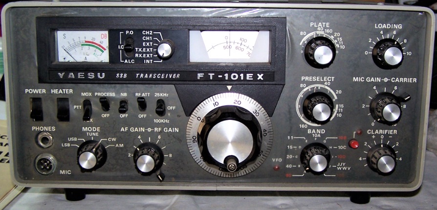
YAESU FT101E VINTAGE TRANSCEIVER UPDATE PART TWO
It is assumed that the radio is in good condition and works perfectly, at least in reception mode, otherwise the installation of the filter does not make sense.
For this installation I helped myself, following the advice, of the instruction manual of the Yaesu FT101E which is available for reading and download here.
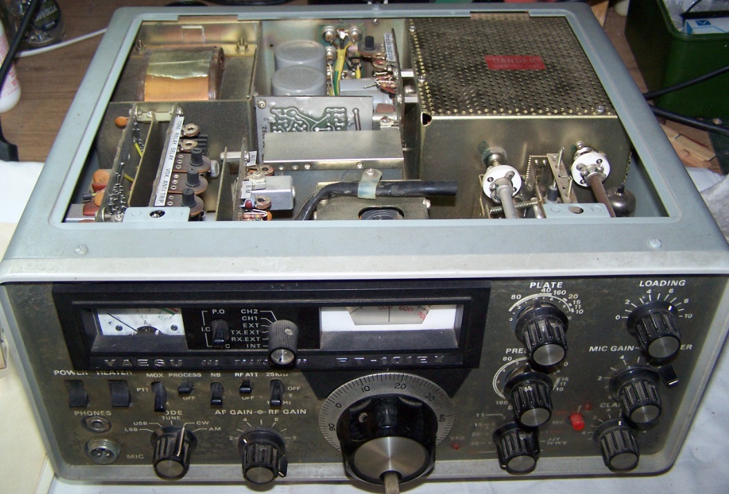
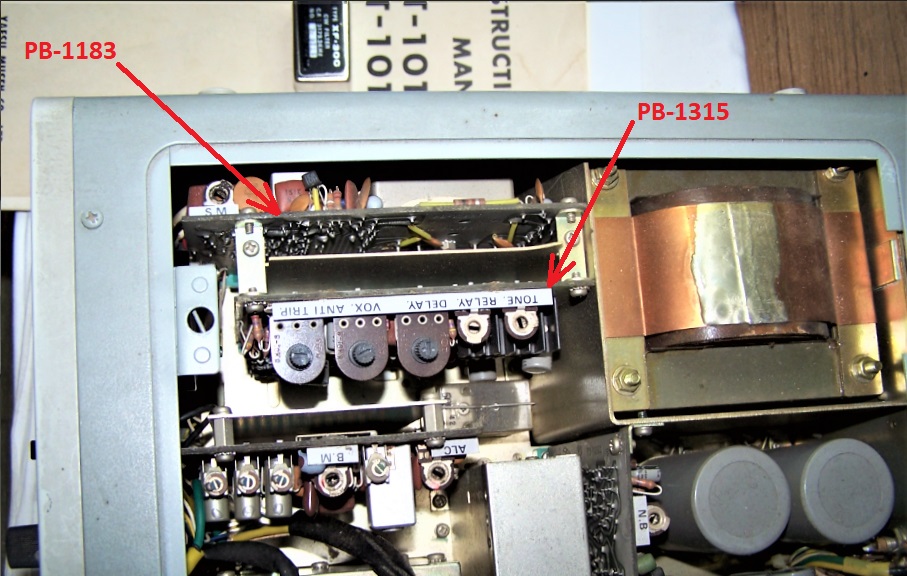
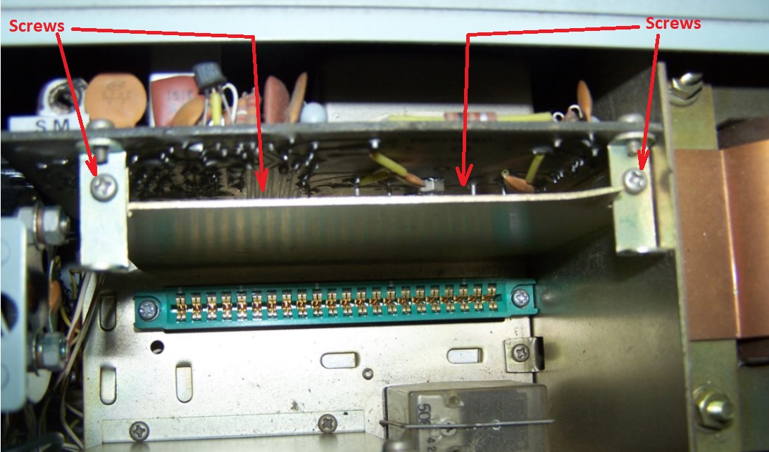
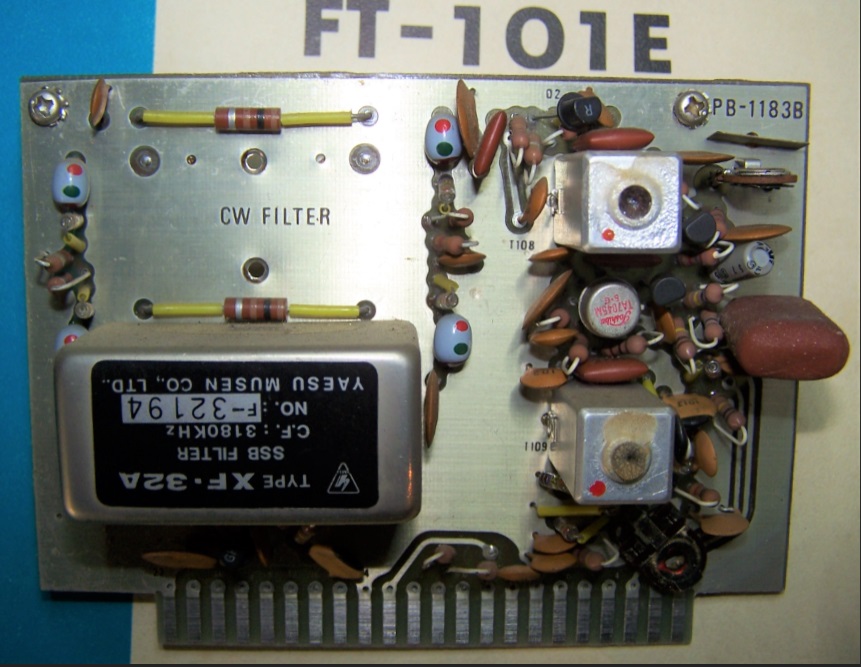
Step one, remove the top cover and locate the two printed circuit boards PB-1315A and PB-1183B inserted vertically by comb, on the left side towards the front panel.
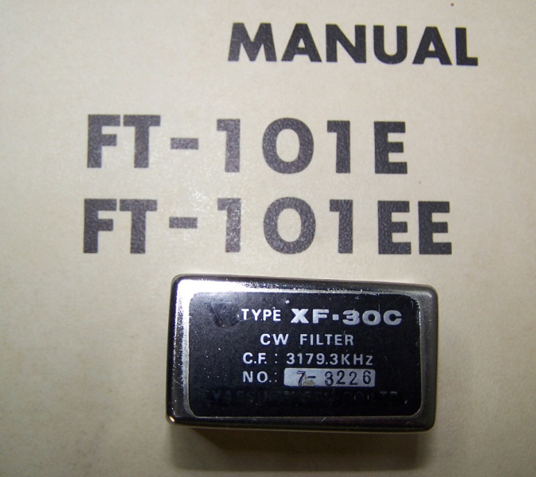
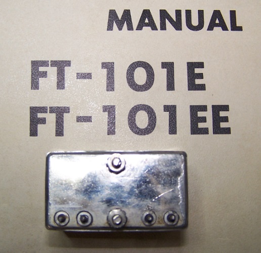
The next four pictures shown the filter XF30C and the location of the two circuit board.
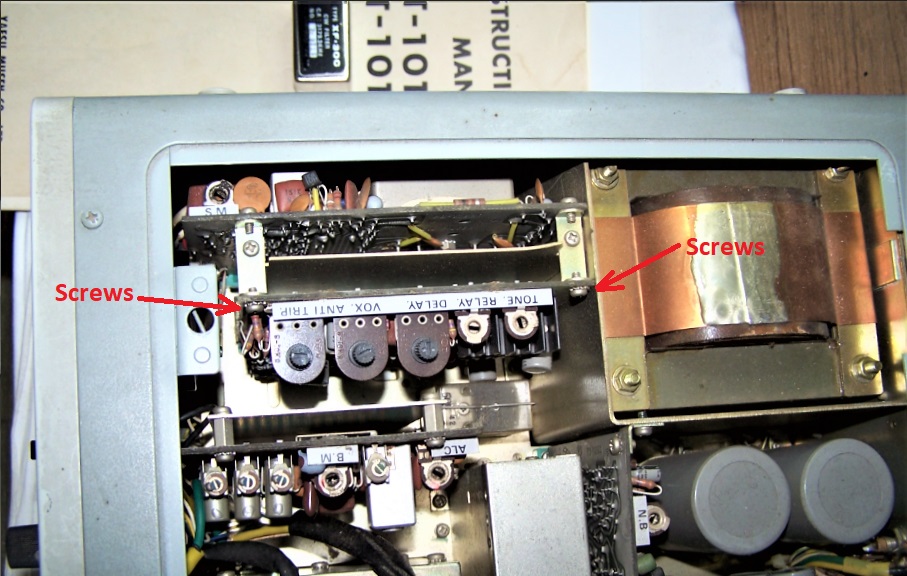
Remove two srews holding PB-1315A to the U shaped bracket. Remove PB-1315A from the chassis connector receptical, gently, rock the circuit board out of the connector.
These operations are shown on the next pictures.
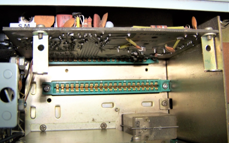
Step two, remove the metal screen between the two circuits. Remove the two screws holding the U bracket to the shied plate. Remove the two screws holdind the shield plate on the bottom and lift out of the cabinet.
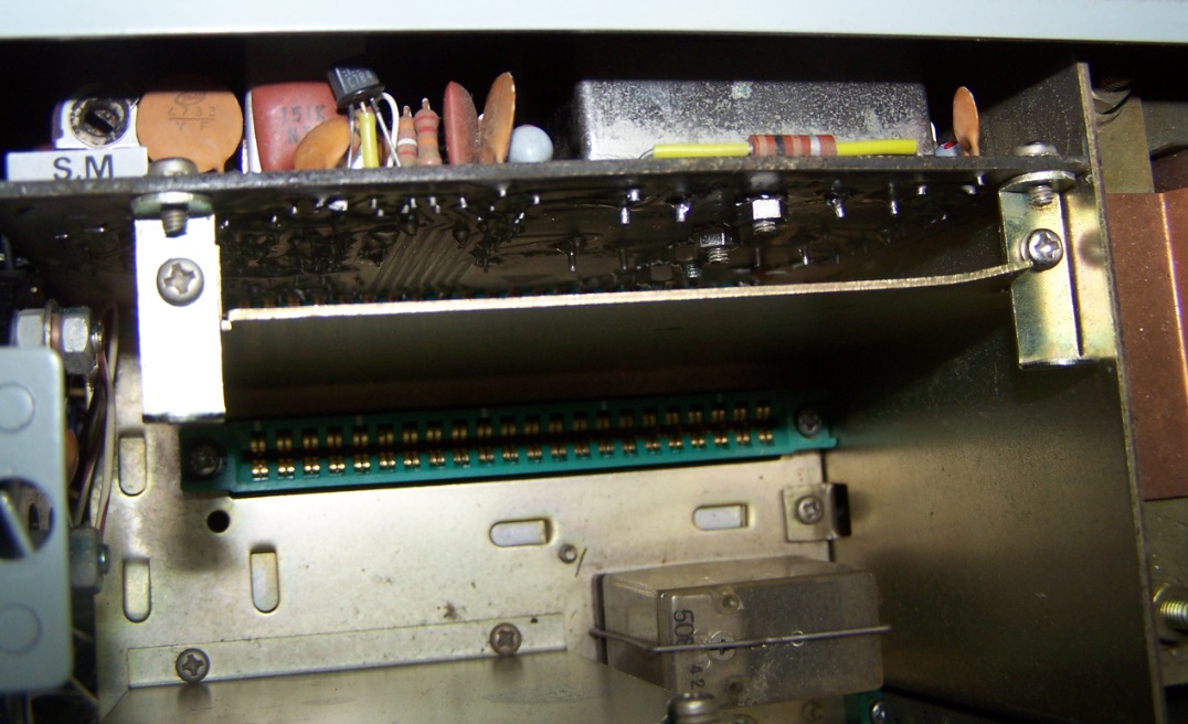
Two more pictures. On the second one we can see the two holes, on the bottom, where the plate shield is fixed. Leave the U shaped brackets attached to the PB-1183A.
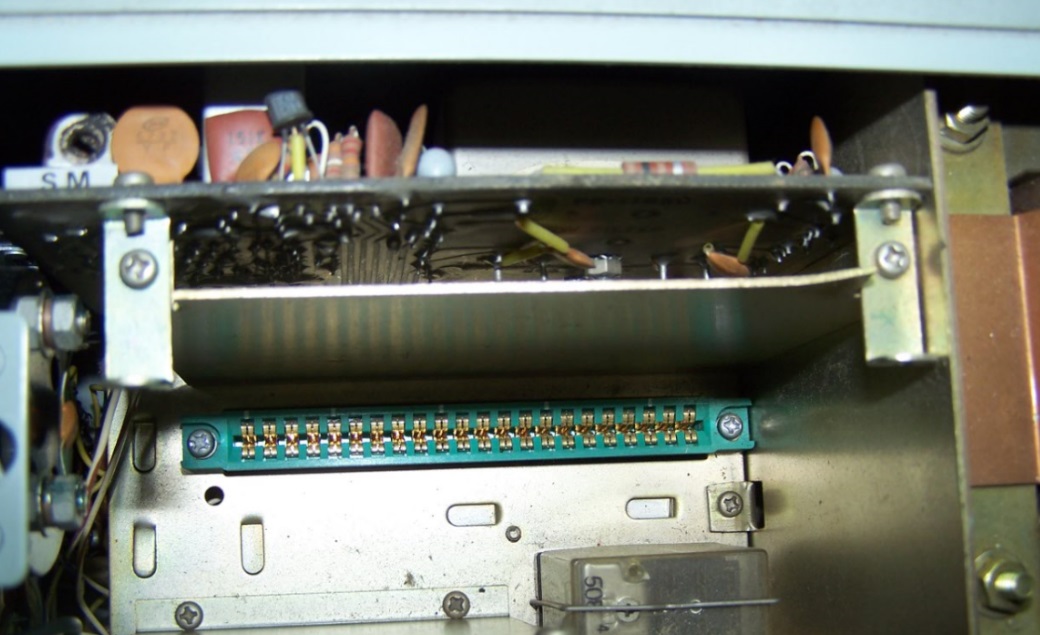
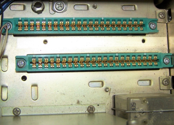
Third step. Grasping the U shaped brackets still attached to the PB-1183A, gently, rock the circuit board out of the connector.
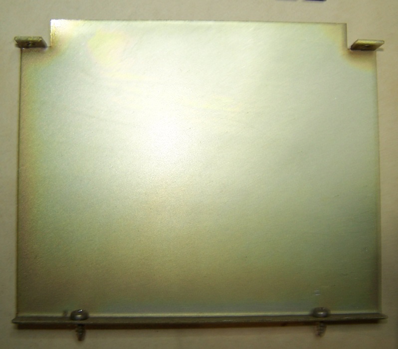
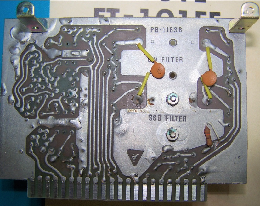
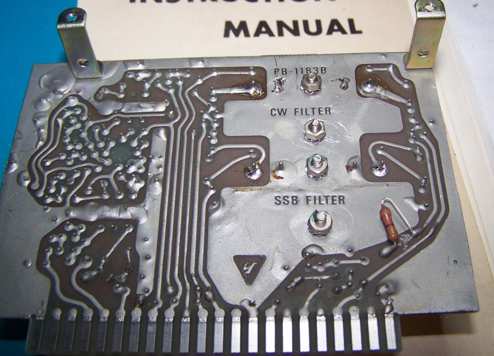
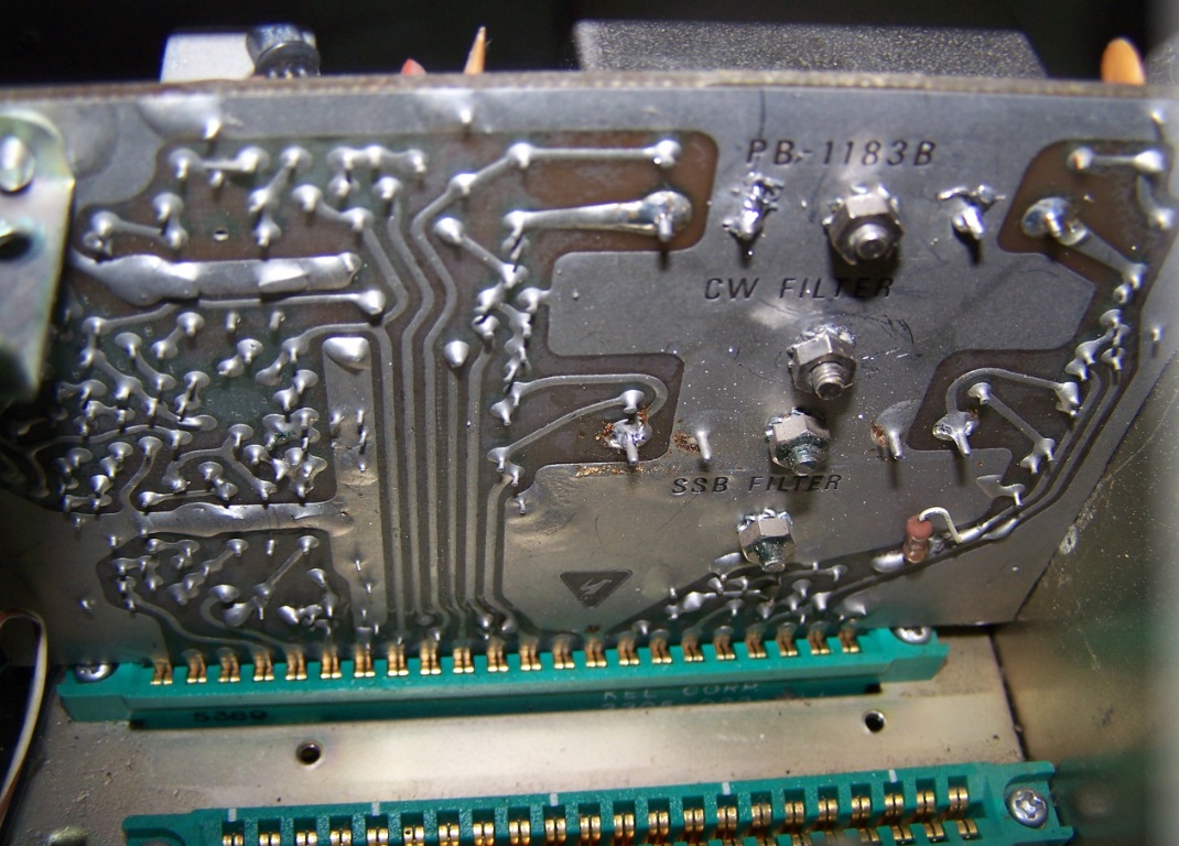
Four more pictures to document the operation just performed. The plate shield, the empty connectors and both side of PB-1183B.
Fourth step, installation of the new XF-30C filter. From the FT101E manual we use this drawing which shows us the guidelines of the work.
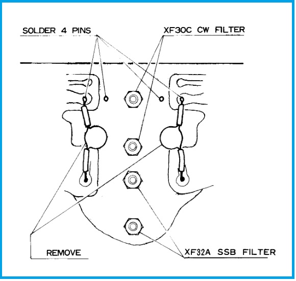
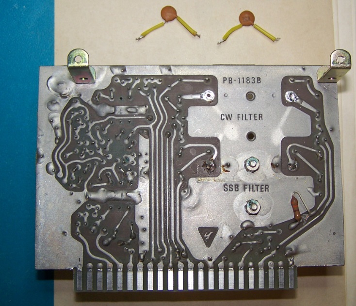
Remove by unsoldering, the two ceramic capacitor C9 and C10 of .01 uF each. Before to install the filter, i had to enlarge the two screws hole from 2,5 mm to 3 mm and the four holes of the filter’s terminals with a 1,2 mm drill bit. Now the filter mathc perfectly all holes therefore i fixed it with nuts and lockwashers provided, at the last i welded the four terminals with a instantaneous solder iron of 120W usind 0.8 mm diameter tin wire.
.
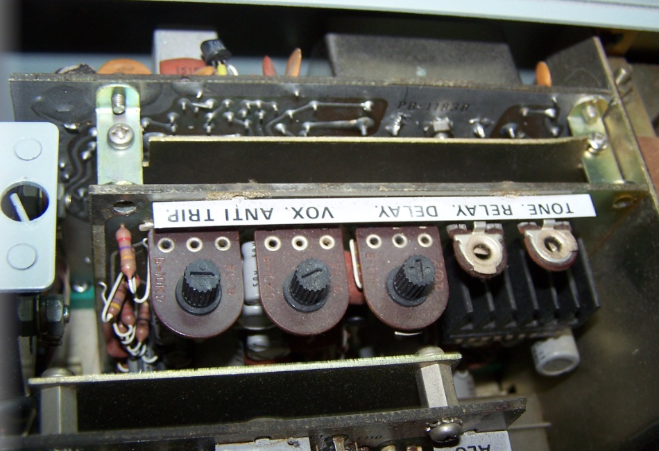
The main job is finished. Now we have to reassemble all components in reverse order. Better to spray a little dry deoxidizer in the empty connectors sockets, even if they are perfectly preserved. In the next picture we see the PB-1183A inserted, from the top appear the CW filter just fitted.
At the end we assemble the plate shield and the PB-1315A, as the photos.
For any requirement or suggestion leave a comment at the end of article or email to: fiorino_i3fdz@yahoo.it
Fiorino/i3fdz


 La mia attività di Radioamatore consiste nella caccia al dx, partecipazione a Contest nazionali e internazionali in HF, ricerca e restauro di apparati storici Vintage.