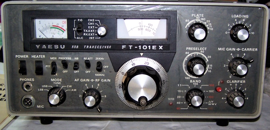
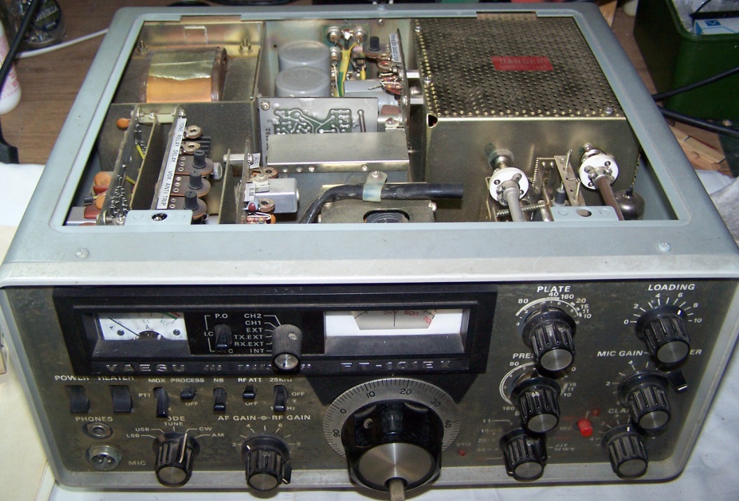
YAESU FT101E VINTAGE TRANSCEIVER UPDATE PART TWO
Si presume che l’apparato sia in buone condizioni e funzioni perfettamente, perlomeno in ricezione, altrimenti l’inserimento del filtro non ha senso.
Per questo lavoro mi sono aiutato, seguendo le istruzioni, del manuale di istruzioni del Yaesu FT101E che è disponibile per la visione e il download qui.
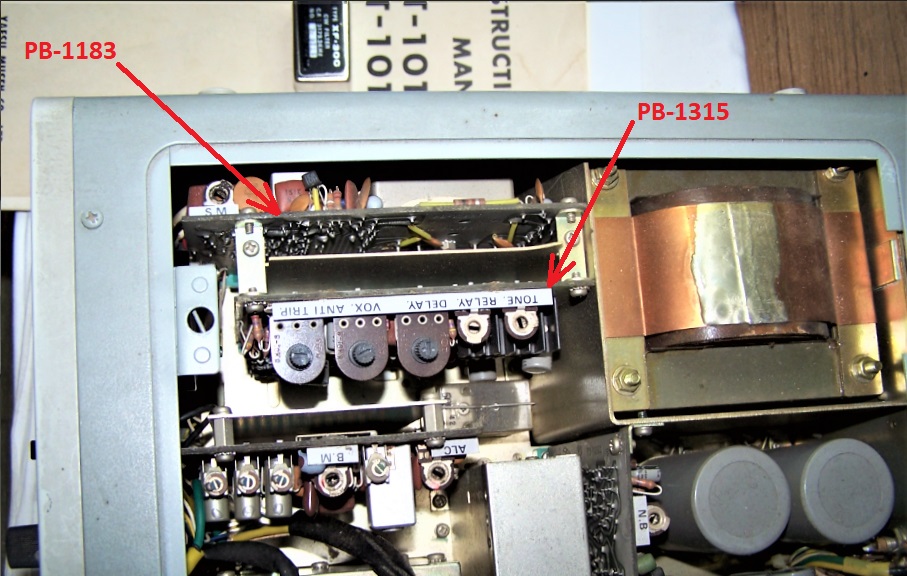
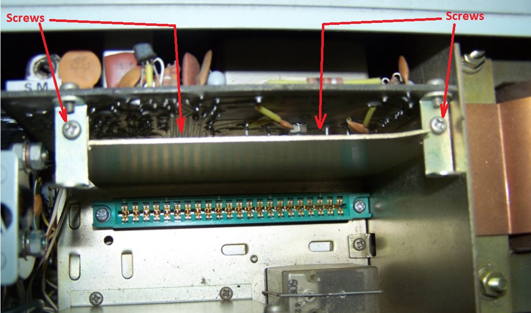
Prima cosa togliere il coperchio superiore e individuare sulla sinistra verso il pannello frontale i due circuiti stampati,interessati, PB-1315A e PB-1183B inseriti verticalmente a pettine.
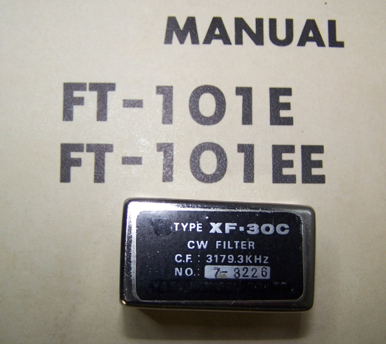
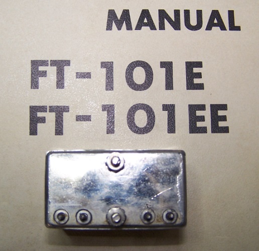
Le prossime quattro foto mostrano il filtro da inserire e l’individuazione dei due circuiti stampati.
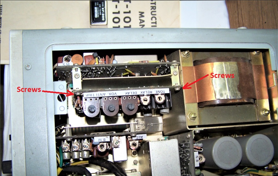
Svitare le due viti che tengono fissato il circuito stampato PB-1315A alla squadretta ad U, adesso si può rimuovere il circuito stampato PB-1315A, estraendolo scuotendolo molto dolcemente dal connettore fissato sullo schassi metallico inferiore.
Le prossime foto illustrano le operazioni.
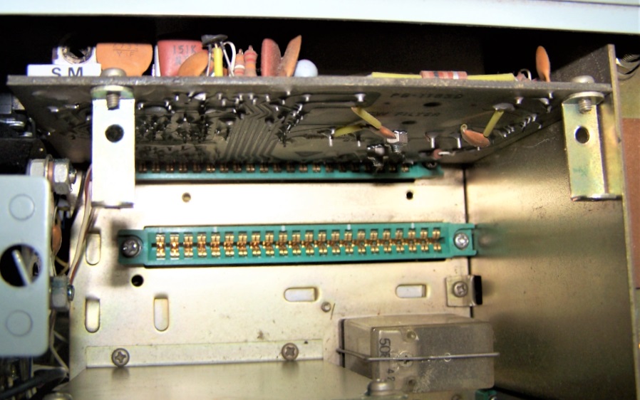
Secondo passo rimuovere lo schermo metallico fra i due circuiti. Svitare le viti al centro delle squadrette ad U che le tengono solidali allo schermo verticale. Togliere anche le due viti sul bordo inferiore ad L dello schermo che lo tengono fissato allo shassi, sfilare lo schermo.
Altre due foto per vedere l’operazione. In particolare nella seconda foto si vedono i due fori dove erano avvitare le due viti nella parte bassa ad L dello schermo. Le squadrette ad U vanno lasciate attaccate al PB-1183A.
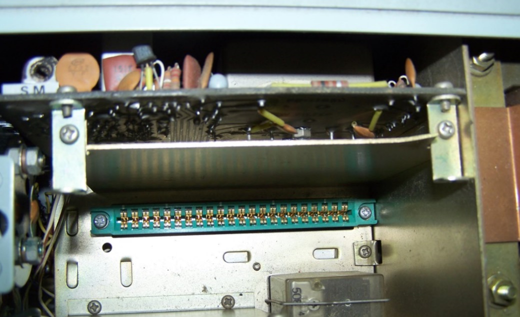
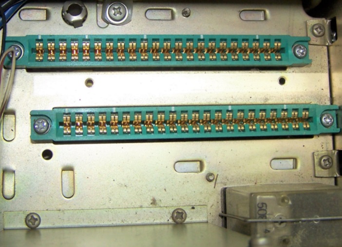
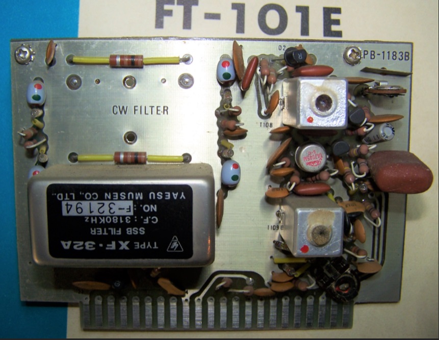
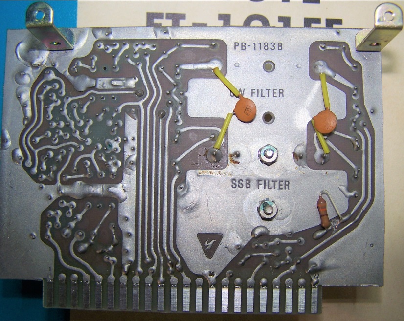
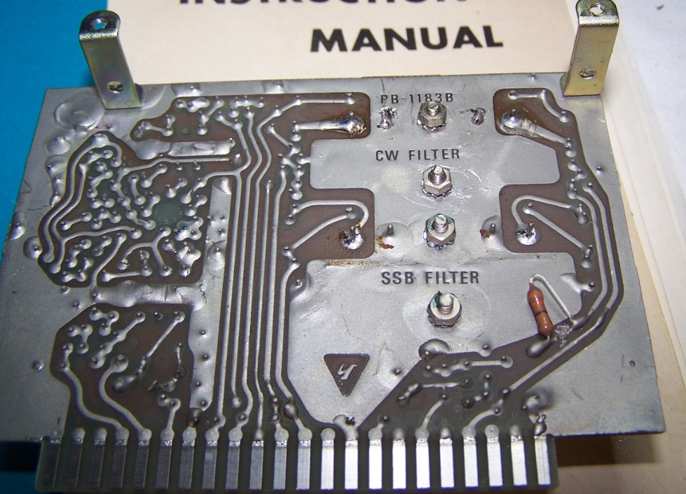
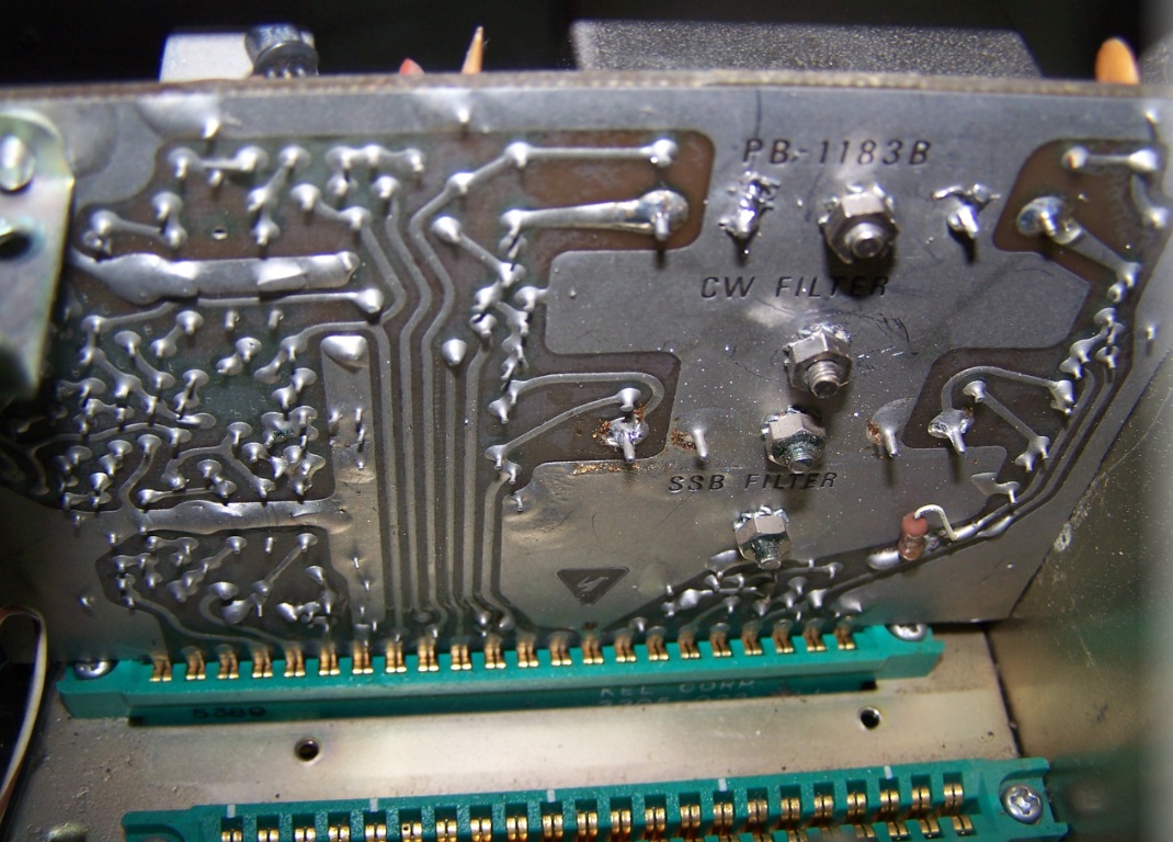
Terzo passo rimozione del circuito stampato PB-1183A, dove bisogna installare il filtro. Lasciando la squadretta ad U fissata al circuito stampato, estrarlo dal connettore fissato sullo schassi metallico inferiore. scuotendolo molto dolcemente.
Altre quattro foto per documentare l’operazione appena terminata. Lo schermo, i due connettori vuoti e entrambi i lati del circuito stampato PB-1183B.
Quarto passo, installazione del nuovo filtro XF-30C. Dal manuale del FT101E abbiamo ricavato questo disegno con le linee guida del lavoro.
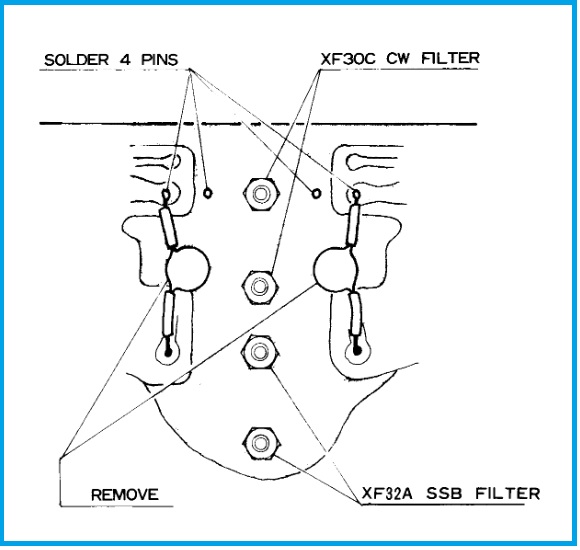
Bisogna dissaldare i condensatori ceramici C9 e C10 dal lato saldature dello stampato PB-1183A. A questo punto inserire il filtroXF-30C nel suo alloggiamento, due viti con dado e rondelle per il fissaggio e i quattro reofori in linea da saldare. Devo dire che ho dovuto ripassare i due fori per le viti con una punta da trapano da 3 mm perchè sul circuito stampato erano da 2,5 mm, poi ho ripassato i fori dei reofori con una punta da 1,2 mm. A questo punto è entrato perfettamente. L’ho fissato con i bulloni e rondelle originali e ho saldato i quattro reofori con un saldatore instantaneo da 120 W usando stagno da 0.8 mm e pasta salda.
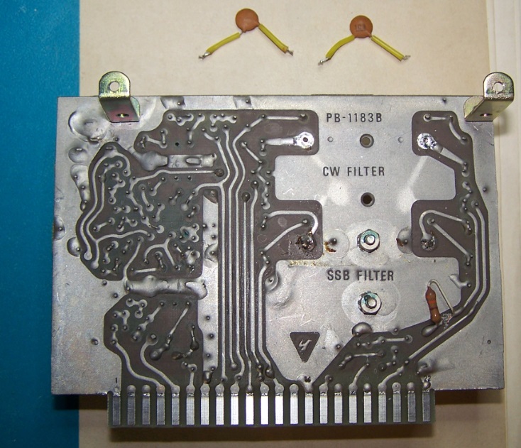
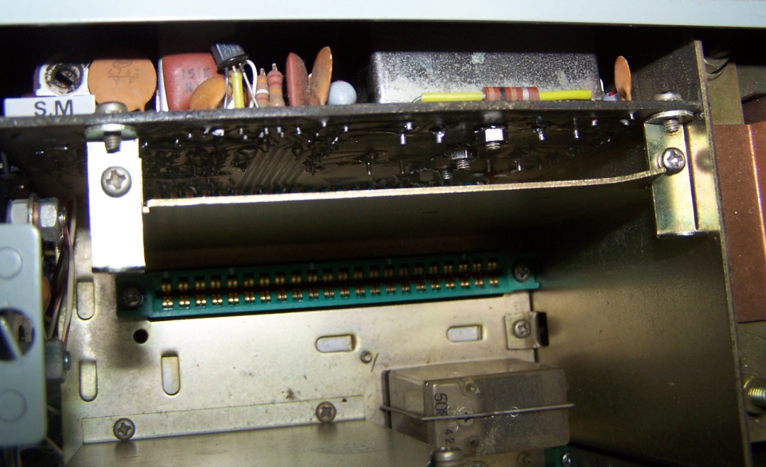
Il lavoro principale è finito. Adesso non resta che rimontare seguendo l’ordine inverso. Prima, però, è meglio spruzzare un pò di disossidante spray secco nei conettori vuoti, anche se si sono conservati perfettamente. Nella prossima foto si vede Il PB-1183A inserito, da sopra si intravvede il nuovo filtro CW.
E per finire si rimonta lo schermo e il circuito stampato PB-1315A. Seguono anche le foto.
Se qualcuno ha qualche richiesta o consiglio, potete lasciare un commento, alla fine di questo articolo o via email: fiorino_i3fdz@yahoo.it
Fiorino/i3fdz


 La mia attività di Radioamatore consiste nella caccia al dx, partecipazione a Contest nazionali e internazionali in HF, ricerca e restauro di apparati storici Vintage.