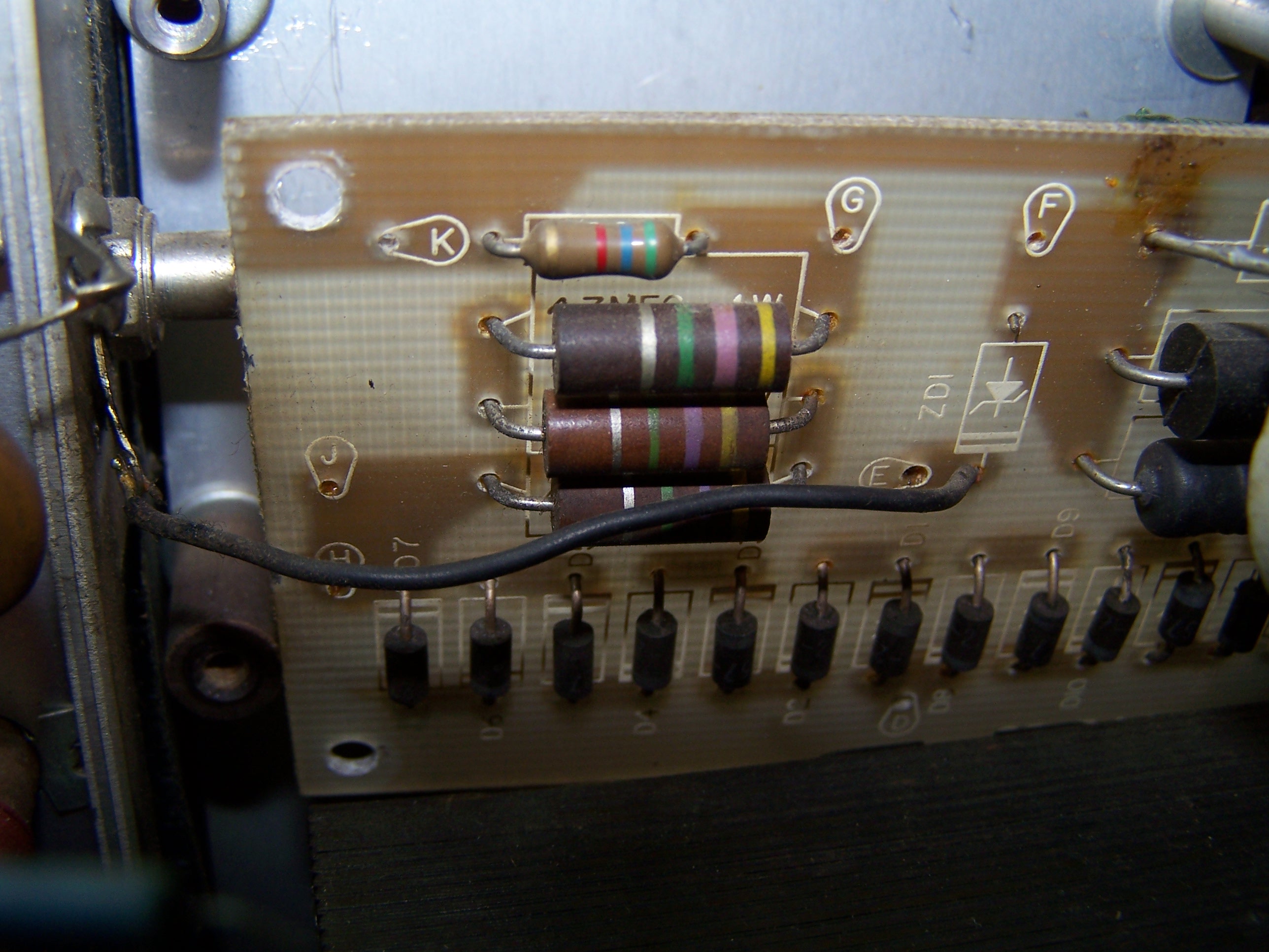
.We can disassemble the old rectifier circuit board. Remove the four screws holding the old rectifier circuit board to the tapped spacers on the capacitor bank bracket. Put the four screws in a safe place. Unsolder old wires from the boad. It don’t require remember the positions. The wires’s colors will help us reconnect them on the new circuit board.
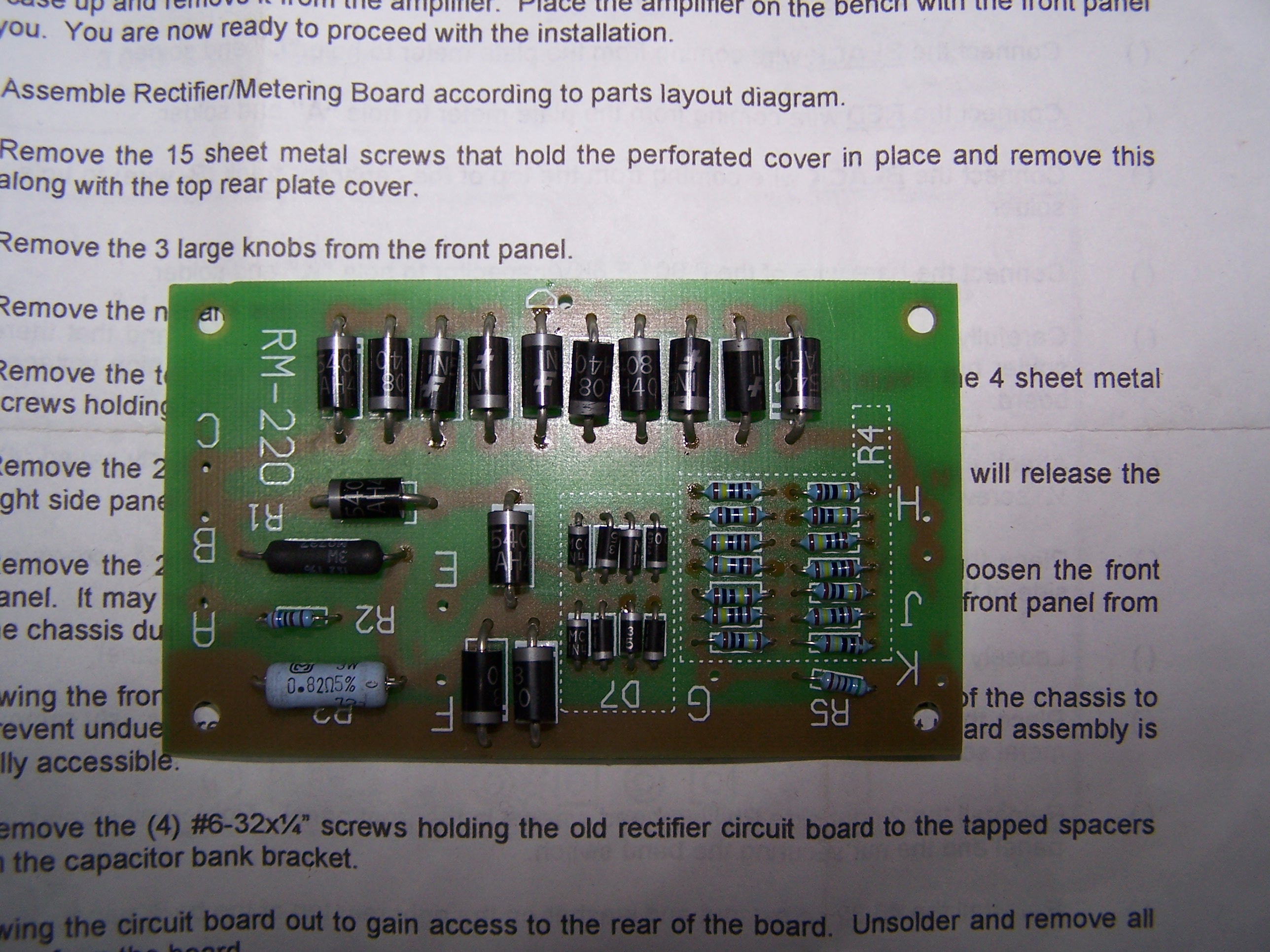
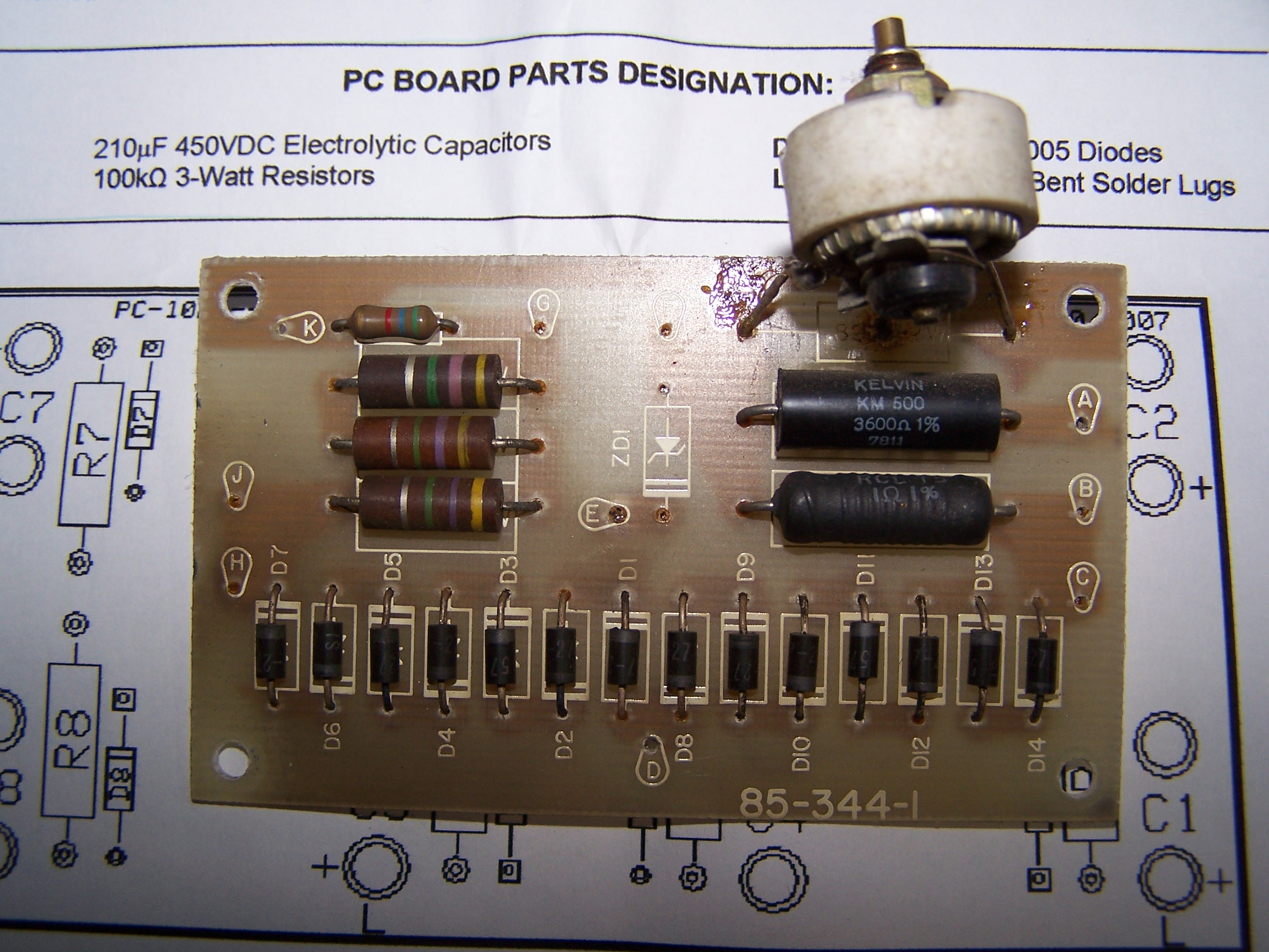
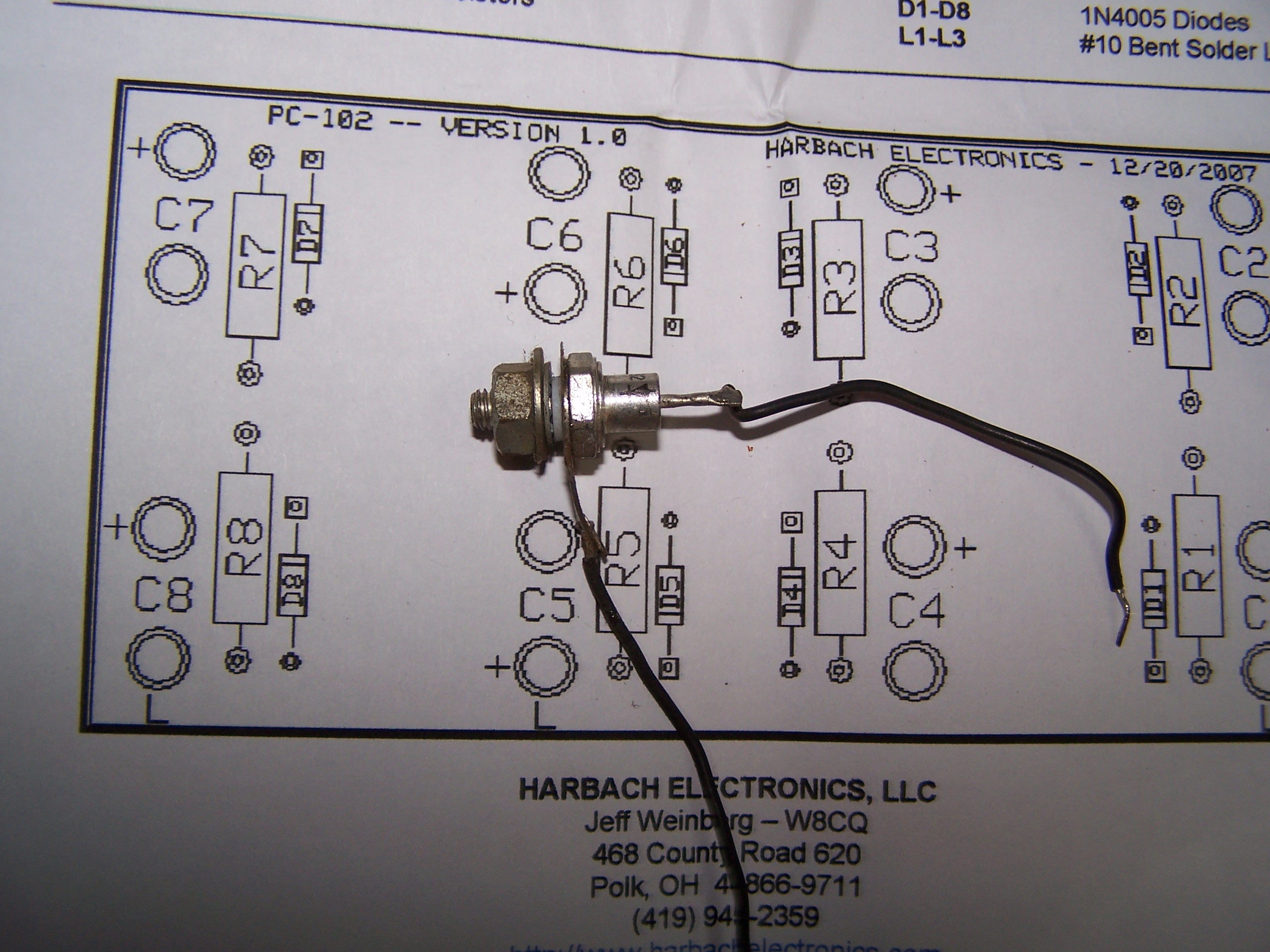
The new circuit board has been built before. So it’s ready to take the place of the old one. Assembling the components on the board is quite easy. We must assure to sold the diodes with correct polarity. Follow the instructions, attached to the Harbach kit RM-220 for Heathkit SB220 power amplifier, carefully. Being careful to solder good.
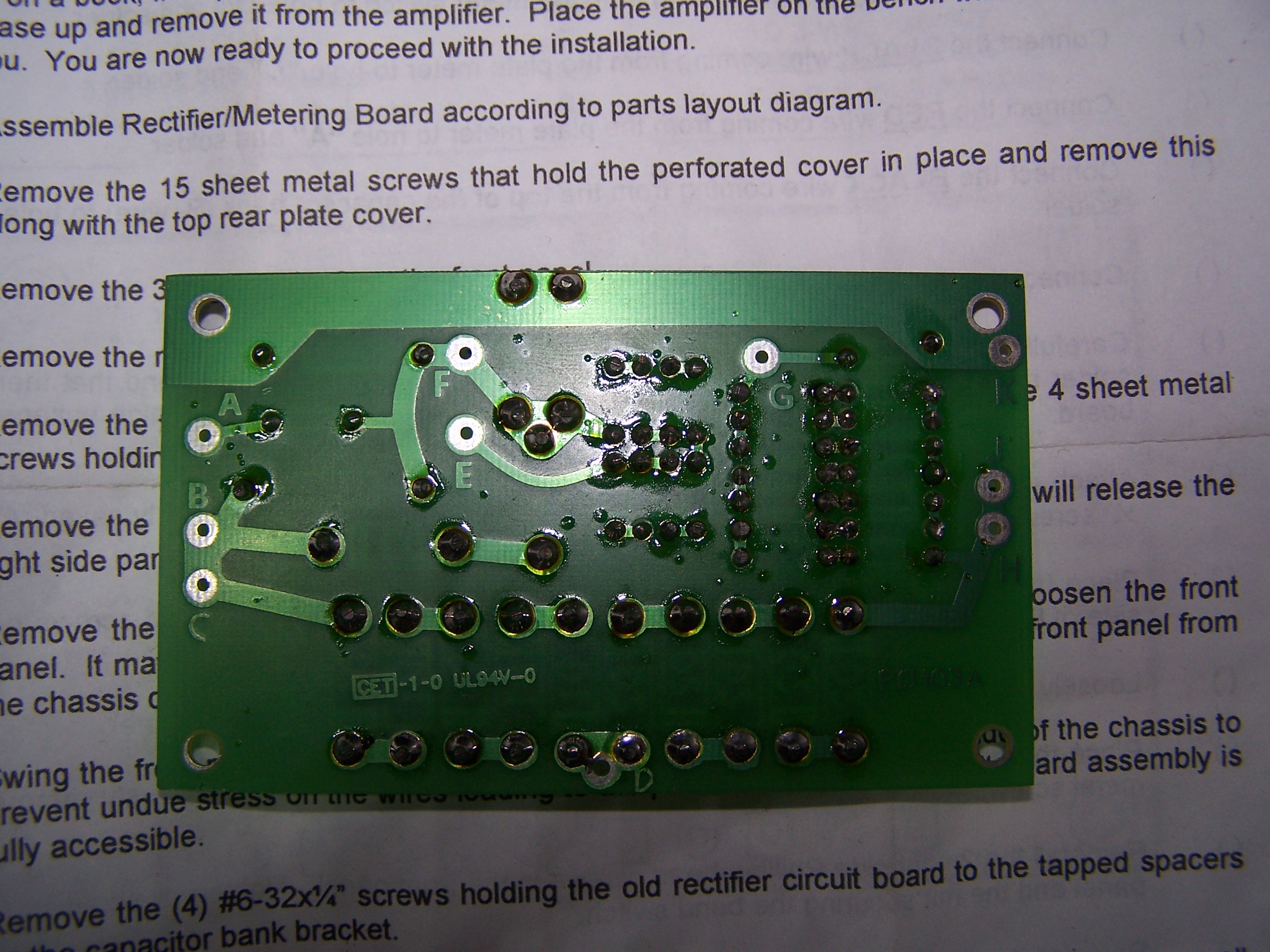
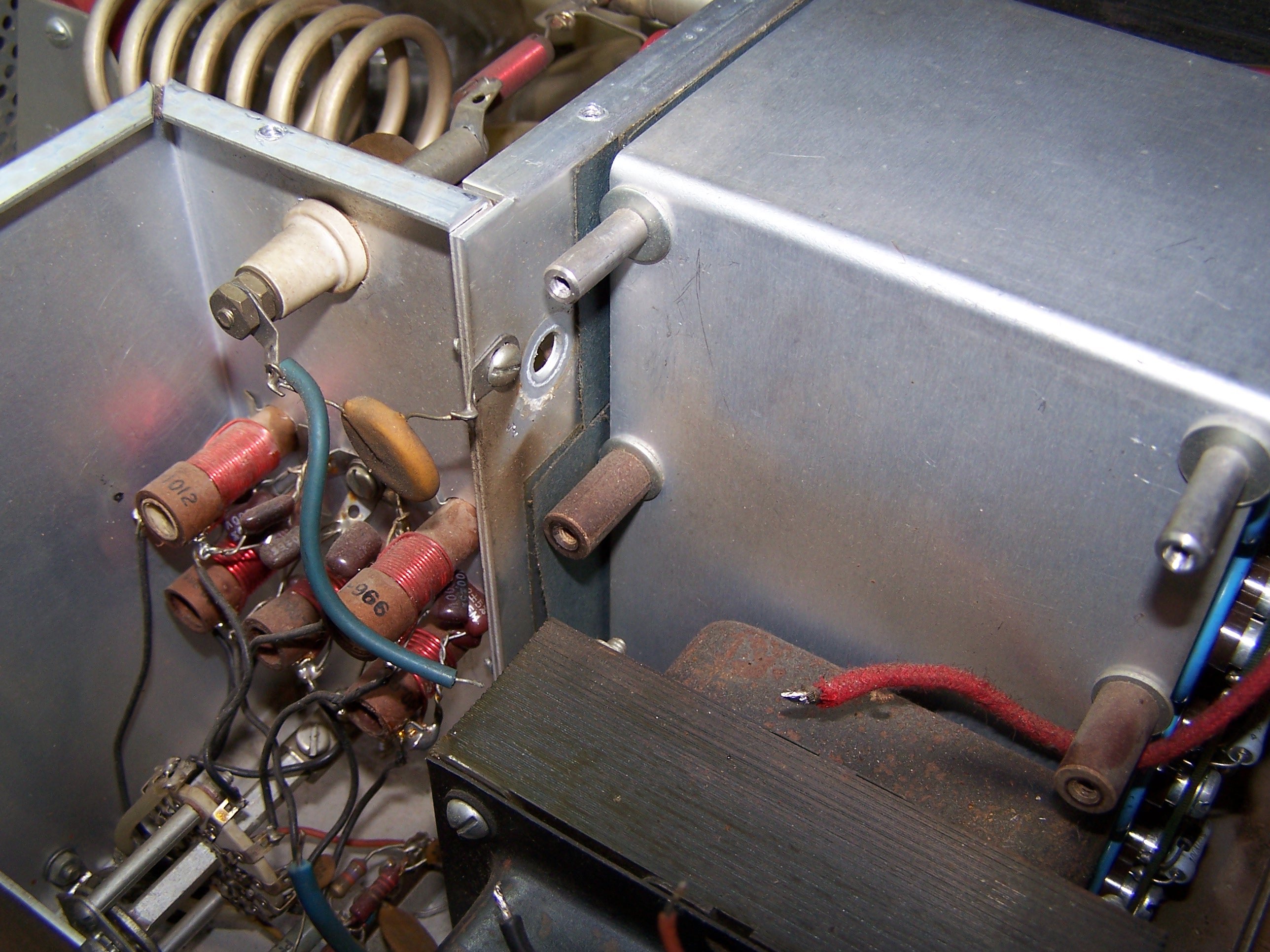
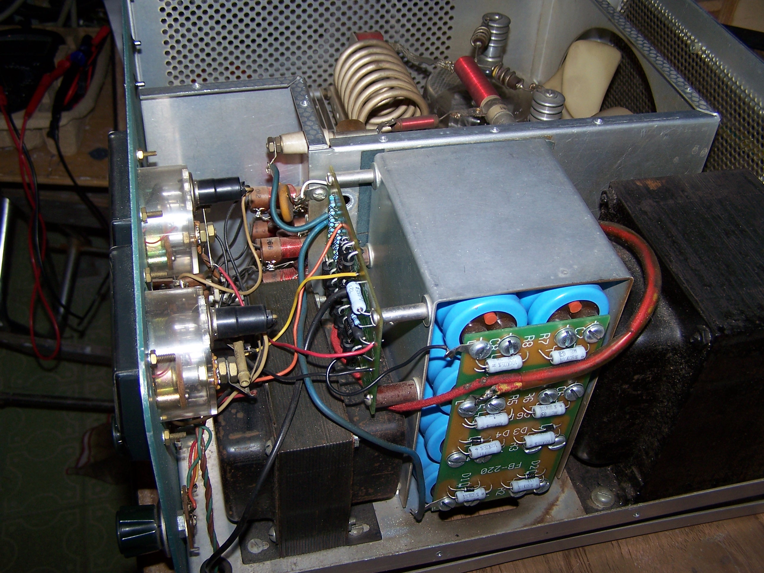
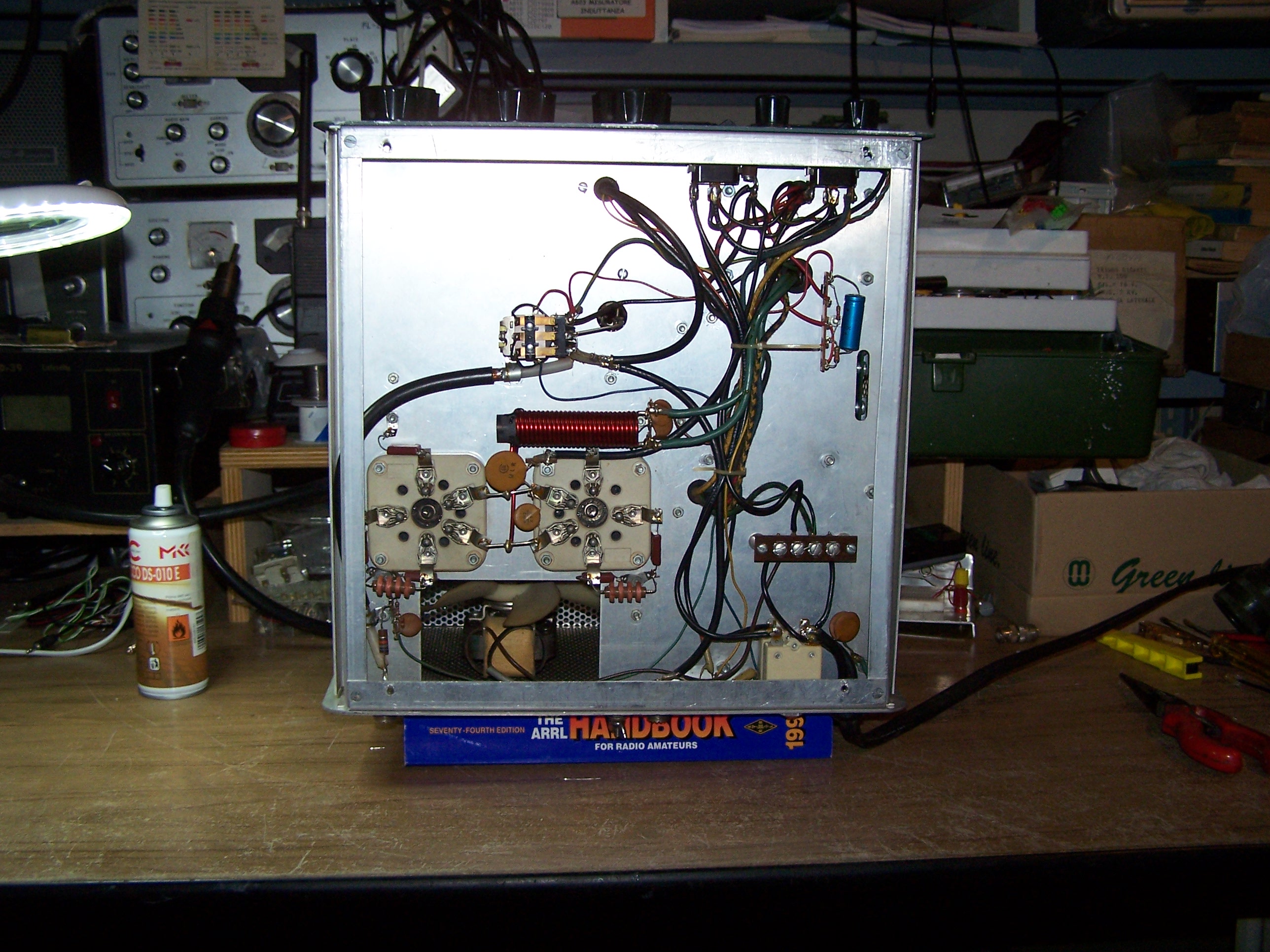
The old circuit board.
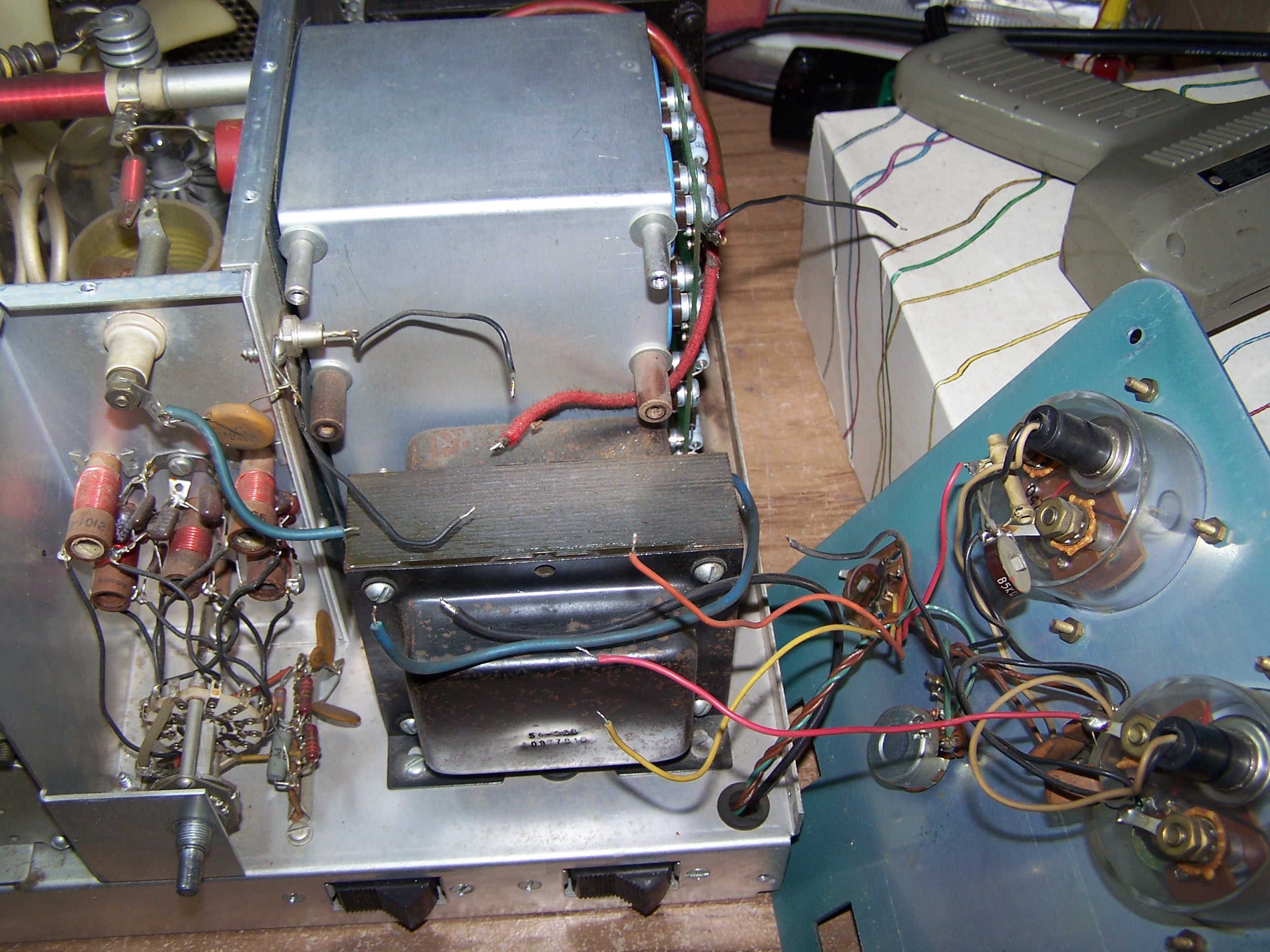
Unsolder the leads going to the zener bias diode. This is mounted behind and to the left of the old rectifier board. The old zener diode is no longer required. Its function has been inserted on the new rectifier system board. It is advisable to remove the old zener diode to eliminate possible high tension arcing due to dangling leads.
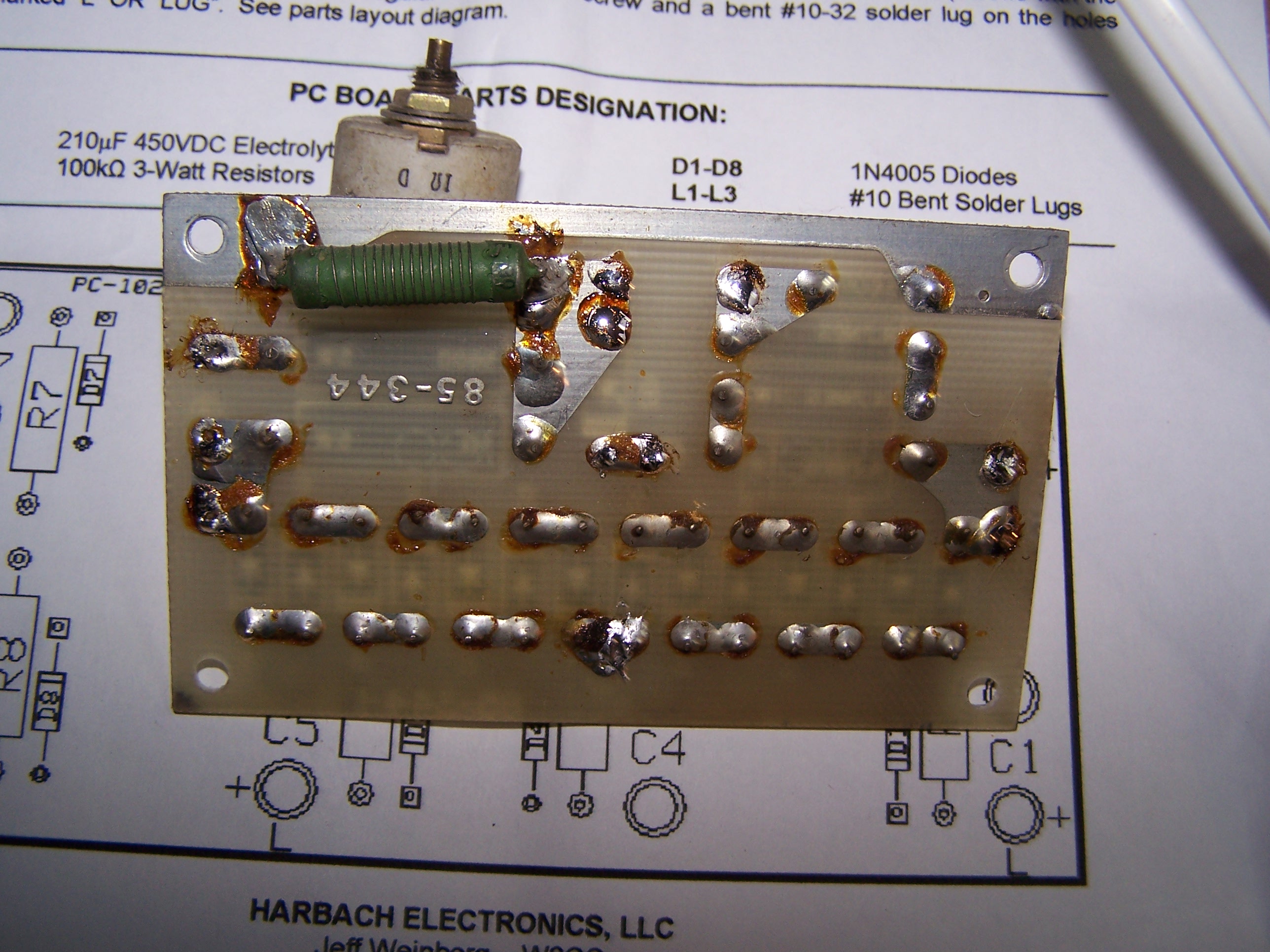
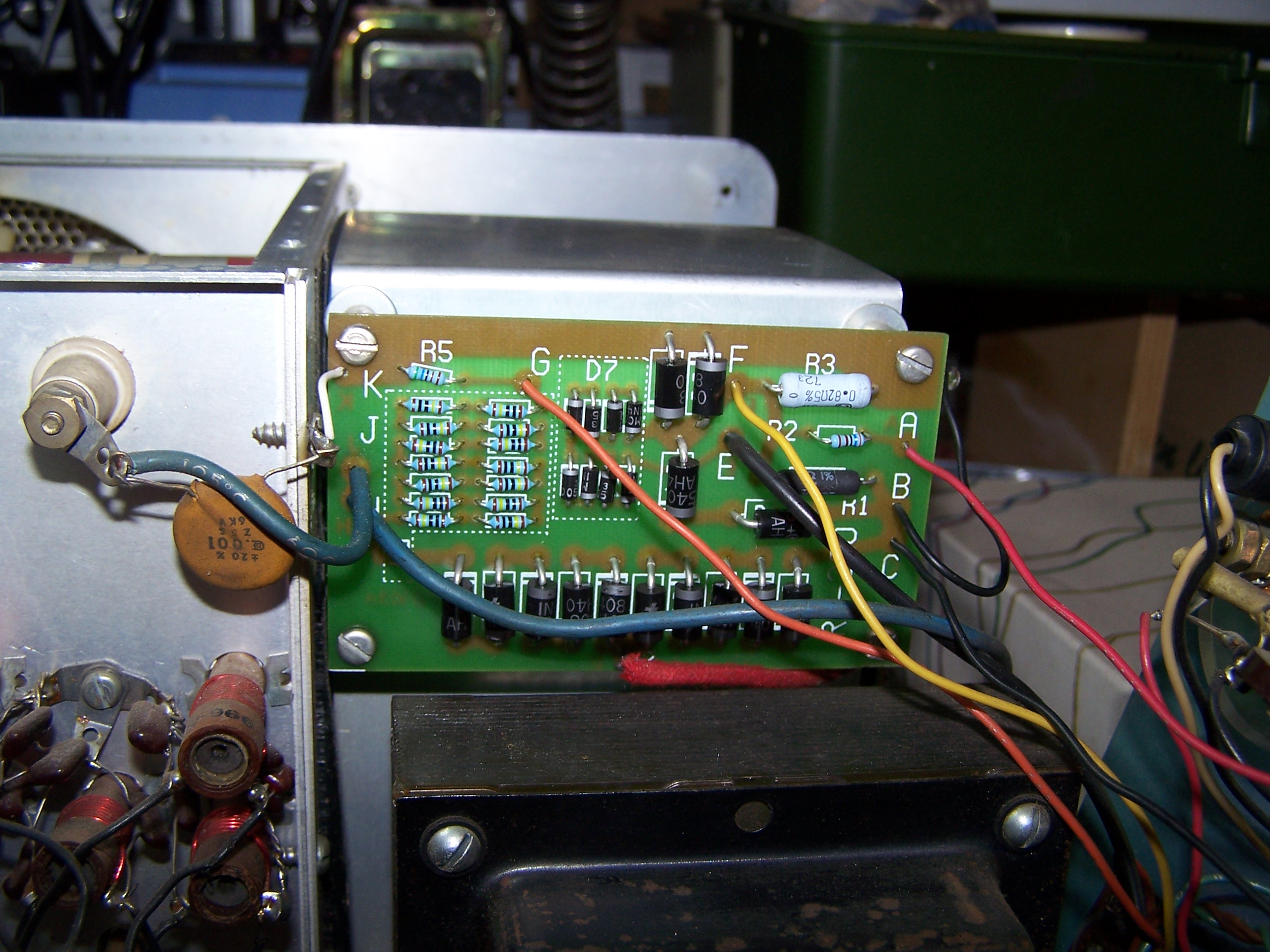
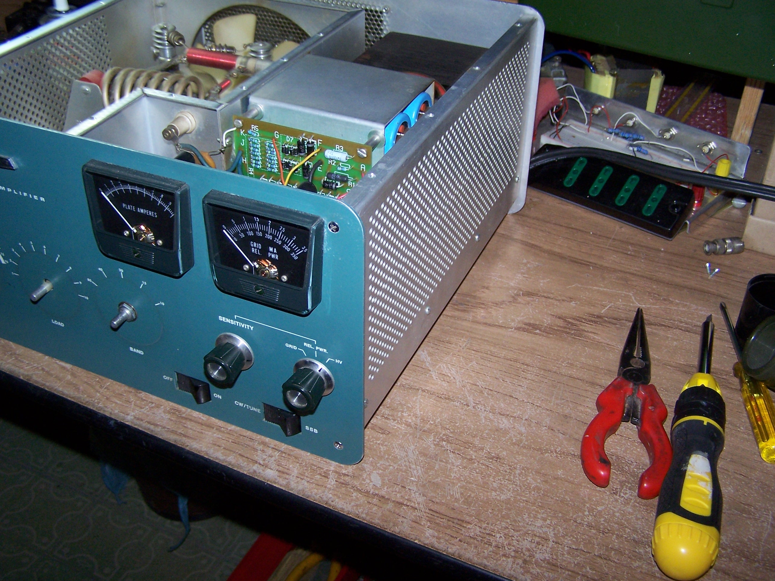
Install the new circuit board. Next steps relate to the solder of leads on new circuit board. All holes are marked with capital letter on the solder side too. They are in a similar location as those on the old rectifier board.
Connect the RED wire, coming from the high voltage transformer, to hole ”D” on the new circuit board and solder.
Connect the HEAVY BLUE wire, coming from the high voltage feed-through insulator on the left, to hole “J” and solder.
Connect the BLUE wire, coming from the bottom of the capacitor bank (the + wire), to hole “H” and solder.
Connect the BLACK wire, coming through the grommeted hole in the chassis (from the relay contact) to hole “E” and solder.
Connect the ORANGE wire, coming from the meter switch, to hole “G” and solder.
Connect the YELLOW wire, coming from the meter switch, to hole “F” and solder.
Connect the BLACK wire, coming from the plate meter, to hole “C” and solder.
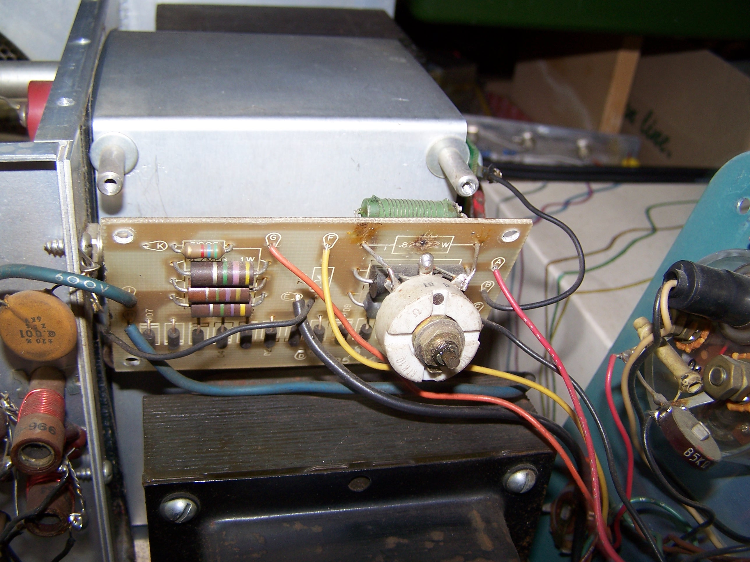
Connect the bare wire of the 0.001F 6KV capacitor to the hole “K” and solder. In my case the capacitor’s bare wire goes to a ground anchorage. I connected a piece of wire from the ground anchorage to the hole “K”. As the photo.

Carefully inspect all solder joints to be sure that both the joints are good and there are no solder bridges which could short components together. Remember you there are very high voltage on this board.
Attach the RM-220 circuit board to the tapped spacers using the previously saved four screws.
Place the front panel back in place and loosely put in the two Phillips-head screws on the left side corners of the front panel.Loosely reinstall the nut and the washer holding the band switch to the front panel.
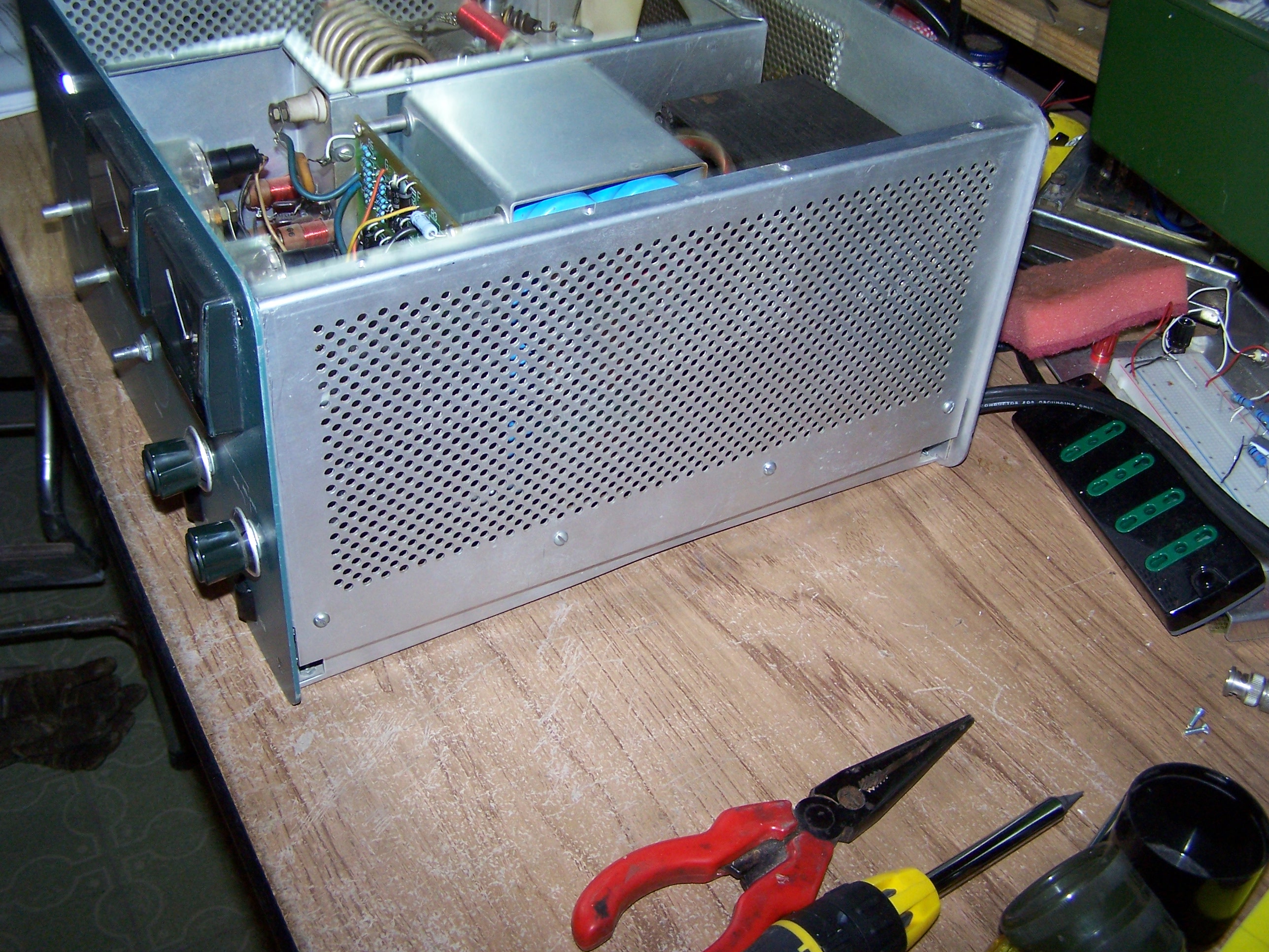
Place the right side panel in position and hold it in place with the four previously removed sheet metal screws.
Reinstall the two right side Phillips-head screws in the front panel. Tighten all screws in the front panel and the nut securing the band switch.
Reinstall the screws, nut and washer on the right rear top of the back panel.
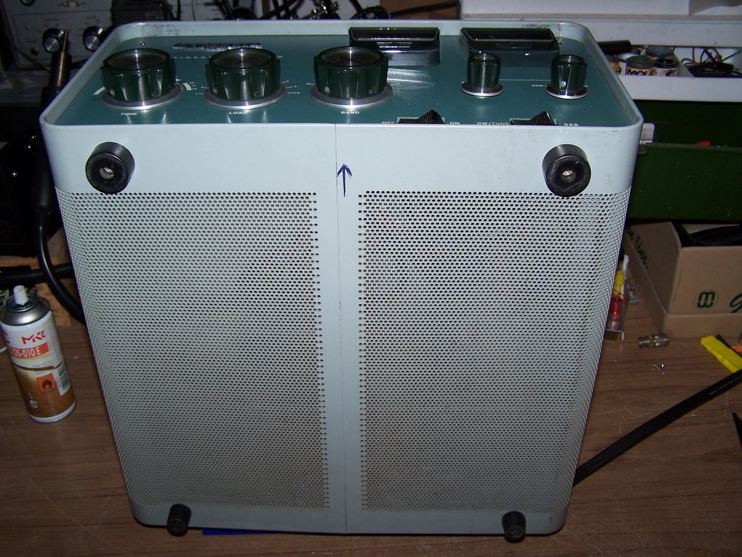
Replace the perforated cover and the top rear plate cover. Reinstall the fifteen sheet metal screws holding these pieces in place. DO NOT over tighten these screws, as it is fairly easy to strip the screw threads in the aluminum underneath. Check if the high voltage short to ground has been removed by the insulated spacer attached to the cover plate.
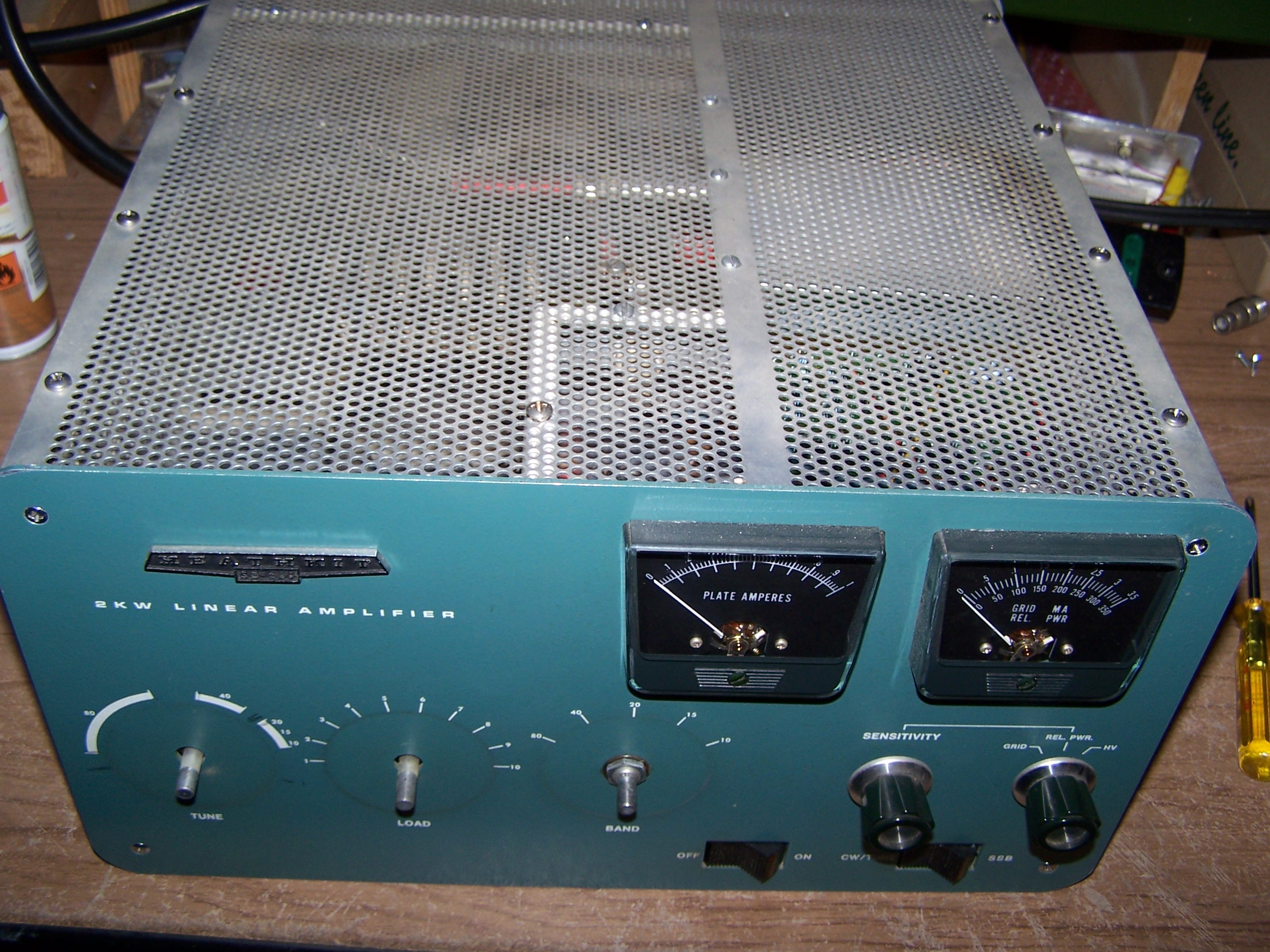
Reinstall the three large knobs on the front panel. Be sure that your pointer orientation is correct on these knobs.
Use the book to hold the amplifier while you reinstall the case and the feet.
The whole job took me eight hours including the kit assembly.
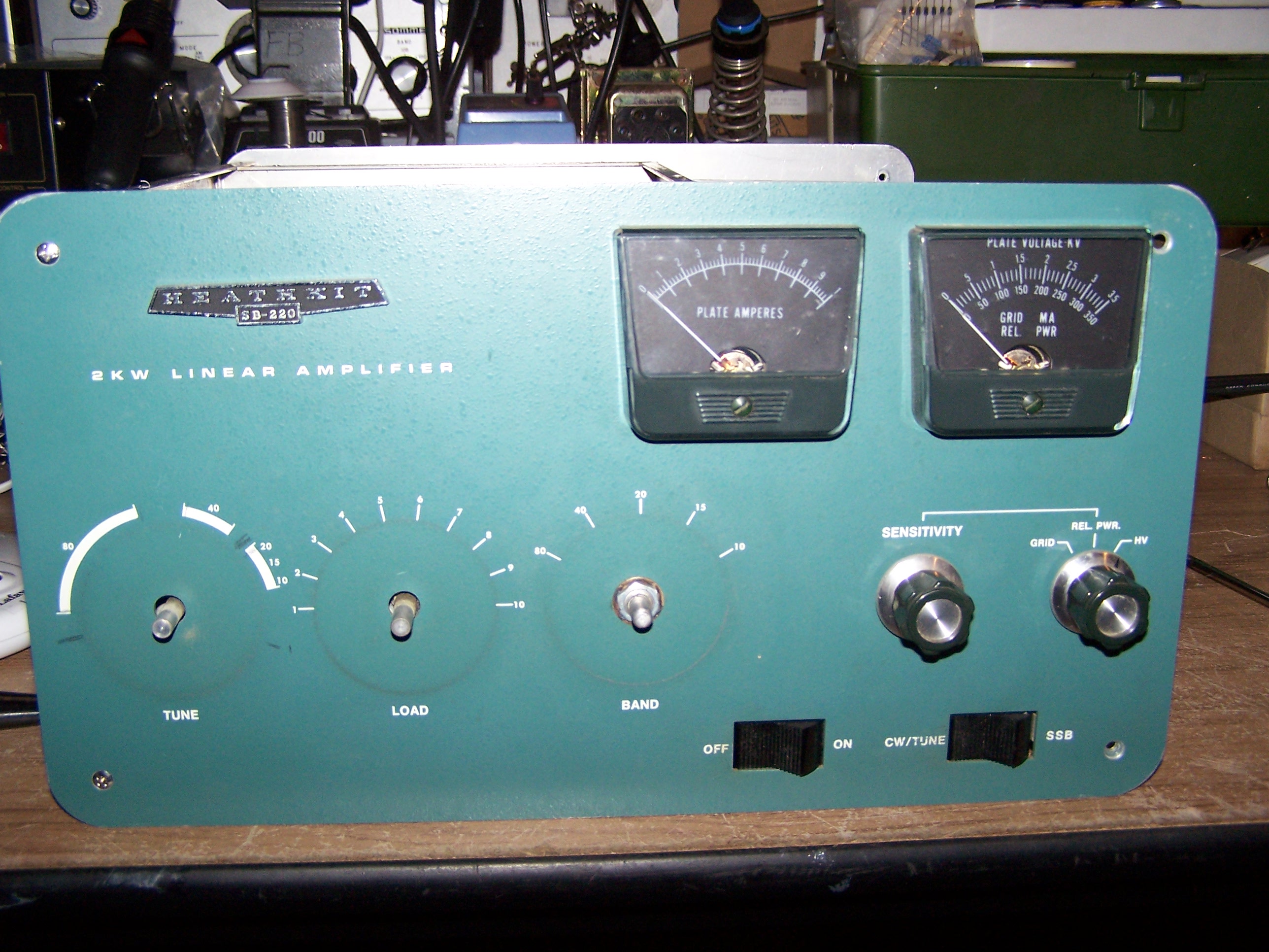
The Heathkit SB220 power amplifier has been checked during the CQWW CW Contest 2016 and the Italian Contest 40/80 CW on December 10 and 11 2016 with very satisfactory results. The amplifier is ready for another forty years of service.
For the English text i used also the notes attached to Harbach Electronics kit RM-220.
Fiorino/i3fdz
Vai alla prima parte Heathkit SB220 power amplifier.
Vai alla seconda parte Heathkit SB220 power amplifier.
Go to part one Heathkit SB220 power amplifier.
Go to the part two Heathkit SB220 power amplifier.

 La mia attività di Radioamatore consiste nella caccia al dx, partecipazione a Contest nazionali e internazionali in HF, ricerca e restauro di apparati storici Vintage.